Beckett CG10(A) Specifiche Pagina 1
Navigare online o scaricare Specifiche per no Beckett CG10(A). Beckett CG10(A) Specifications Manuale Utente
- Pagina / 32
- Indice
- SEGNALIBRI
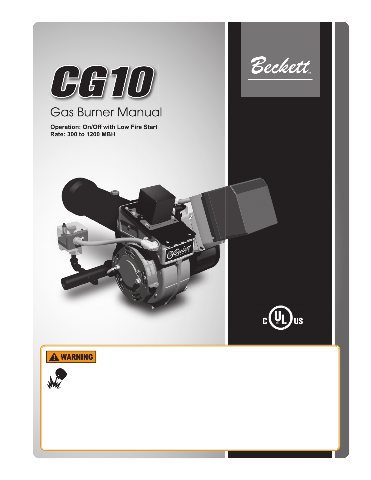
- COMMERCIAL PRODUCTS 1
- Contents 2
- General Information 3
- Pre-installation Checklist 5
- Minimum Combustion 6
- Chamber Dimensions (inches) 6
- Maximum Capacity, MBH 7
- Figure 5. Burner Dimensions 8
- Mount the Burner 9
- Connect Gas Piping 9
- GAS UTILITY PIPING 10
- FACILITY PIPING 10
- GAS TRAIN BURNER 10
- Wire the Burner 12
- Sequence of Operation 13
- Prepare the Burner for 13
- Start-up 13
- Start-up checklist 14
- CG10 Burner Manual 15
- Start the Burner 16
- Section: Start the Burner 17
- Pressure Drop, In. WC 19
- Rate, MBH 19
- Maintenance and Service 22
- For the OPERATOR 27
- Replacement Parts 28
- Burner Confi gurations 29
- Air Platform Confi gurations 30
- Limited Warranty Information 32
Sommario
COMMERCIAL PRODUCTSFire, Explosion and Asphyxiation HazardsFailure to follow these instructions exactly could lead to fi re or explosion and result in
10Figure 7. Typical Gas Piping LayoutSchedule 40 metallic pipe with 0.50 psi or less inlet pressure and 0.30” W.C. pressure dropMaximum capacity in cu
11CG10 Burner ManualFigure 8. UL gas train confi gurationMSCUPRSSOVSSOV1MLTC UBURNERC6097BHGPSTPC6097ALGPSTCTCMSCSSOV1 PRSSOV MLTCUUTPTC TCHGPSLGPSABBR
12Wire the BurnerInstall the burner and all wiring in accordance with the National Electric Code ANSI/NFPA 70 (Canada CSA C22.1) and all applicable co
13CG10 Burner ManualInitiate – The primary control enters the INITIATE sequence when the control is fi rst powered on or power returns after an interru
14Start-up checklistVerify the following before attempting to start the burner:1. General Carefully read and become familiar with the CG10 Manual, F
15CG10 Burner ManualSection: Prepare the Burner for Start-upFigure 10. CG10 component familiarizationMajor ComponentsItem Description1 Jacking Screw2
16Start the Burner Burner start procedure (Before proceeding, turn off and lock out electrical power and close the main leak test cock to shut off ga
17CG10 Burner ManualTable 2. Initial burner settingsNotice: The settings in this chart are for reference only. The actual conditions at the installati
18Estimating RateManifold to Furnace Pressure information can be used to estimate the burner’s fi ring rate when it is not possible to clock a meter fo
19CG10 Burner ManualFigure 12. Manifold to Furnace Pressure Drop vs. Rate - Stepped Spud DesignFigure 13. Manifold to Furnace Pressure Drop vs. Rate -
2ContentsGeneral Information ... 3Hazard Defi nitions: ...
20High limit – To check the High Limit, raise the temperature or pressure of the operating control to a higher level and lower the limit to a setting
21CG10 Burner ManualVerify that all boiler sections, canopy, and access plates or doors are fully equipped with gaskets and sealed against any leakage
22Burner:Run the burner and perform a complete combustion test using the proper instruments before proceeding. If necessary refer to the section label
23CG10 Burner ManualAdjust the burner for proper combustion:Follow the guidelines under “Start the Burner” to set the combustion levels using test ins
24Figure 14A – Gas Gun AssemblyBurner Head Adjustment - There is an optimum gas orifi ce size and burner head setting for each fi ring rate of the CG10
25CG10 Burner ManualPropane Restrictor Description The Beckett Propane Restrictor Conversion Kit allows for the conversion of CG10 burners for use wit
26Refer to Figures 15 and 16 when performing the following steps.Remove the jacking screw (B) from the air tube/manifold assembly to free the internal
27CG10 Burner ManualTest/Inspection Frequency CommentsInspect area surrounding heating plant Daily Keep area clean and free of clutterInspect gas supp
28Replacement PartsFor best performance specify genuine replacement parts.Item Description Part #1 Ignition Transformer 7503U2 Control Subbase See N
29CG10 Burner ManualBurner Confi gurationsThe CG10 burner is offered in confi gurations that allow it to be customized to the capacity and furnace size
3CG10 Burner ManualHazard Defi nitions:General InformationIndicates a hazardous situation which, if not avoided, will result in death or serious injury
30Section: Burner Confi gurationsThe table below shows proven combinations of the components and the nominal fi ring rate ranges they serve. These comb
31CG10 Burner Manual
USA: P.O. Box 1289 ● Elyria, Ohio 44036Canada: R.W. Beckett Canada, Ltd. ● Unit #3, 430 Laird Road ● Guelph, Ontario N1G 3X7www.beckettcorp.comPart Nu
4Professional Installer’s Responsibility:Section: General InformationFollow these instructions exactly.Failure to follow these instructions could lead
5CG10 Burner ManualFigure 1. Burner NameplatePre-installation Checklist If there is risk of the space being under negative pressure, or of exhaust fan
6Flange mounting arrangement (Includes high-temperature gasket and /or fi ber rope for pressure fi ring).Verify fi ring input rangeRefer to appliance man
7CG10 Burner Manual400500600700800900100011001200130014000 0.2 0.4 0.6 0.8 1Furnace Pressure, In. W.C.Maximum Capacity, MBHCG10.6SCG10.5SCG10.4SCG10.3
8Figure 5. Burner DimensionsBurner Model Airtube Dim. A Dim. B O.D.10.1 - 10.3, 10.1S - 10.3S 51927 25.0” 11.7” 4.43”10.4 - 10.6, 10.4S - 10.6S 51961
9CG10 Burner ManualMount the burner to the appliance. The burner specifi ed for packaged equipment will have a fl ange welded for the required insertion
Prodotti e manuali riguardandi no Beckett CG10(A)
 (12 pagine)
(4 pagine)
(12 pagine)
(4 pagine)

 (12 pagine)
(1 pagine)
(2 pagine)
(2 pagine)
(2 pagine)
(2 pagine)
(12 pagine)
(1 pagine)
(2 pagine)
(2 pagine)
(2 pagine)
(2 pagine)
 (2 pagine)
(1 pagine)
(2 pagine)
(6 pagine)
(18 pagine)
(2 pagine)
(1 pagine)
(2 pagine)
(6 pagine)
(18 pagine)
© 2020, manymanuals.it. Tutti i diritti riservati | 0.070 s |
 Manymanuals.com
 Manymanuals.de
 Manymanuals.fr
 Manymanuals.it
 Manymanuals.pl
 Manymanuals.cz
 Manymanuals.es
 Manymanuals-pt.com
Commenti su questo manuale